Cable for inductive detection loops
The detection of a vehicle by a detector is generally done by means of an inductive loop embedded in the roadway.
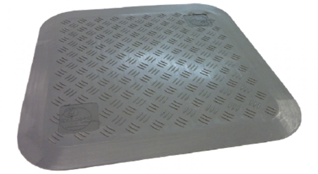
If it is not possible to groove the floor (e.g.: waterproofing), the recessed loop can be replaced by a detection pad fixed to the surface (for light vehicles only).
In order for a loop to be effective and to match the vehicle detector to which it is connected, it must be made taking into account the value of certain parameters, namely:
- type of cable used,
- perimeter of the loop,
- number of turns constituting it,
- loop/detector distance (feeder).
Technical characteristics:
- The loop:
The loop consists of a single-stranded, multi-stranded copper cable insulated with
section of at least 1.5 mm². Its perimeter is between 3 and 20 m. For a conventional track, a perimeter of 5 to 6 m is recommended. The loop must be rectangular, with the longest side perpendicular to the direction of travel. The recommended height is 1 m. Typically, the width of the loop is equal to the width of the track, subtracting 300 mm from each side. When the track width is very large, it is preferable to connect two loops rather than one large one in order to obtain optimum sensitivity. The space between the two loops is at least 1 m.

- The feeder:
The feeder is the connecting cable between the loop and the detector. It is made of the same cable as the loop, but twisted at a rate of 20 turns per meter. Ideally, the length of the feeder should not exceed 15 m. However, it is possible to go up to a distance of 100 m maximum. However, the sensitivity of the loop gradually decreases with the increase in the length of the feeder. In this case, it is necessary to compensate for this loss by adding a turn or two to the loop. When the feeder is very long or when it runs with other low-voltage conductors, it is recommended to use a cable with a screen. The screen is earthed on the detector side.

FACILITY:
The loop is inserted into a groove 10 to 15 mm wide and 30 to 40 mm deep. The corners of this groove are broken to avoid damage to the cables. An additional groove is made from a corner of the loop to the side of the track to route the feeder to the detector. The grooves will then be filled with rapid cement, black epoxy resin or bitumen mastic.
Static metal masses do not interfere with the operation of the detector, but they reduce its sensitivity. It is then possible to compensate for this loss by adding one or two turns to the loop.


Solutions in the same category
Other Parking management system that might capture your interest
