Accessories

Parking management system

Accessories

Discover our selection of accessories to optimize your parking management system, including traffic lights, vehicle detectors, detection loops and studs, and displays.

Signal lights

LED spotlights in 100, 200 or 300 mm diameter housings

Vehicle detectors

Single, dual or multi-channel, they are connected to inductive loops embedded in the roadway to count vehicles, manage automatic barriers, traffic lights or gates, etc.

Détecteurs de véhicule monocanal DP132 – DP134 - ACCOR EMEA

DP132 – DP134 Single Channel Vehicle Detectors

The DP132 (230V AC) – DP134 (12V-24V DC) are microprocessor-based single-channel loop detectors specifically designed for parking and counting and access control applications.

Its main functions are to detect the presence of the vehicle by means of a change in inductance caused by the passage of the vehicle over an inductive loop buried under the road surface.

The DP132 and DP134 incorporate an automatic sensitivity amplification option that ensures trouble-free installation and improved sensitivity to facilitate reliable detection of high-body vehicles and SUVs.


The strong points of the DP132 – DP134 inductive loop detector:

  1. Automatic sensitivity amplification

The automatic sensitivity amplification function allows the loop detector to automatically select the best operating sensitivity which will achieve better detection regardless of the vehicle type.


  1. Isolation protection

The loop isolation transformer provides protection against lightning and transient damage.


  1. Selectable permanent presence

The presence relay output will be kept activated during detection, configurable as 'normally open' or 'normally closed'.

This function prevents premature re-closing of the barrier or gate when the vehicle is still on the detection loops.


  1. Filtered

It can be activated to delay detection and avoid the detection of small objects (trolleys, safety shoes, etc.) passing over the loop.


  1. Areas of application

Single-channel detectors can be used in various parking and motorized obstacle applications:

- Safe for retractable barriers and bollards.

- Manage free exits from the parking lot at barriers and gates.

- Provide vehicle presence information at access control or toll booths.

- Provide the impulses necessary for vehicle counting.

- For use with parking ramp management systems.

Détecteurs de véhicule bi-canal DP232/DP234 - ACCOR EMEA

DP232/DP234 dual-channel vehicle detectors

The DP272 (230V AC) and DP274 (12V – 24V AC) are microprocessor-based dual-channel detectors specifically designed for parking and counting and access control applications.

Their main function is to detect the presence of the vehicle by means of a change in inductance caused by the passage of the vehicle over an inductive loop buried under the road surface.

The DP272 and DP274 incorporate a unique automatic frequency selection option that ensures trouble-free installation and improved sensitivity to facilitate reliable detection of high-body vehicles and SUVs.


The strong points of the DP272 – DP274 inductive loop detector:

  • Automatic frequency

The AFS (Automatic Frequency Selection) feature allows the loop detector to automatically select the best operating frequency that will result in the lowest loop noise and maximum signal strength.


  • Diagnostic capacity

The optional DT-DU700 Bluetooth module allows you to retrieve all the information needed to establish a complete diagnosis via an application on a tablet or smartphone.

The DU Diagnostics app is available for free on the App Store and Google Play.


  • Sensitivity

Several sensitivity levels are possible, making these detectors the most sensitive.

Detection of unwanted small objects such as bicycles and trolleys can be eliminated by selecting lower sensitivity levels.

Low axle vehicles and vehicle/trailer combinations will not lose detection.


  • Power failure memory

Infinite retention of loop detector state memory in case of power failure. This feature can be enabled and disabled via the 'Reset' push button.


  • Isolation protection

The loop isolation transformer provides protection against lightning and transient damage.


  • Presence or pulse output

One relay output per channel configurable as presence or pulse, 'normally open' or 'normally closed'.


  • Direction of passage with DP272 and DP274 loop detectors

This option allows you to indicate the direction of passage of the vehicle. Very practical for counting applications.

Displays

With 5 or 7 digits, they indicate how full a parking lot is thanks to an integrated differential counter. They display the number of free spaces in green, and “COMPLET” or “FULL” in red when this is the case.

Vehicle detection loop and stud

For reliable vehicle detection and optimal parking management

Cable pour boucles de détection inductive - ACCOR EMEA

Cable for inductive detection loops

The detection of a vehicle by a detector is generally done by means of an inductive loop embedded in the roadway.

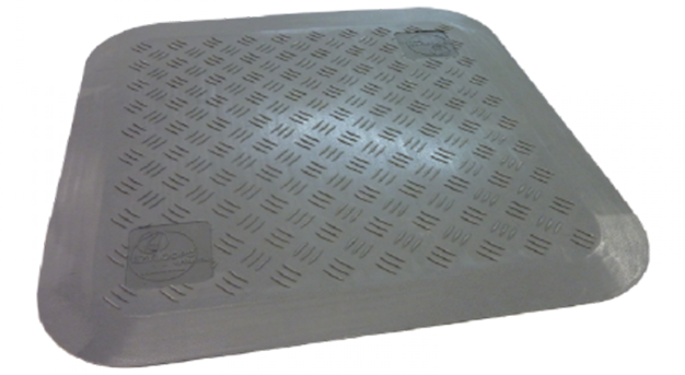
If it is not possible to groove the floor (e.g.: waterproofing), the recessed loop can be replaced by a detection pad fixed to the surface (for light vehicles only).

In order for a loop to be effective and to match the vehicle detector to which it is connected, it must be made taking into account the value of certain parameters, namely:

  1. type of cable used,
  2. perimeter of the loop,
  3. number of turns constituting it,
  4. loop/detector distance (feeder).


Technical characteristics:

  1. The loop:

The loop consists of a single-stranded, multi-stranded copper cable insulated with

section of at least 1.5 mm². Its perimeter is between 3 and 20 m. For a conventional track, a perimeter of 5 to 6 m is recommended. The loop must be rectangular, with the longest side perpendicular to the direction of travel. The recommended height is 1 m. Typically, the width of the loop is equal to the width of the track, subtracting 300 mm from each side. When the track width is very large, it is preferable to connect two loops rather than one large one in order to obtain optimum sensitivity. The space between the two loops is at least 1 m.


  1. The feeder:

The feeder is the connecting cable between the loop and the detector. It is made of the same cable as the loop, but twisted at a rate of 20 turns per meter. Ideally, the length of the feeder should not exceed 15 m. However, it is possible to go up to a distance of 100 m maximum. However, the sensitivity of the loop gradually decreases with the increase in the length of the feeder. In this case, it is necessary to compensate for this loss by adding a turn or two to the loop. When the feeder is very long or when it runs with other low-voltage conductors, it is recommended to use a cable with a screen. The screen is earthed on the detector side.


FACILITY:

The loop is inserted into a groove 10 to 15 mm wide and 30 to 40 mm deep. The corners of this groove are broken to avoid damage to the cables. An additional groove is made from a corner of the loop to the side of the track to route the feeder to the detector. The grooves will then be filled with rapid cement, black epoxy resin or bitumen mastic.

Static metal masses do not interfere with the operation of the detector, but they reduce its sensitivity. It is then possible to compensate for this loss by adding one or two turns to the loop.


Request a quote